Moon Pointer Project
This is a project that I began in August of 2025. The “Moon Pointer” that (you guessed it) points at the moon. What makes this project a little more involved is that it does not use the internet, but rather Lunar Theory.
Skills
| Skills | ||
|---|---|---|
| Astronautics | CAD | Python |
| C/C++ | Microcontrollers (RP Pico) | PCB Design (KiCAD) |
The Development Board
The most difficult part of this project by far (as a non-electrical engineer) was the creation of the development board. Thankfully, Raspberry Pi has a hardware design manual that served as a crutch for this portion of the project.
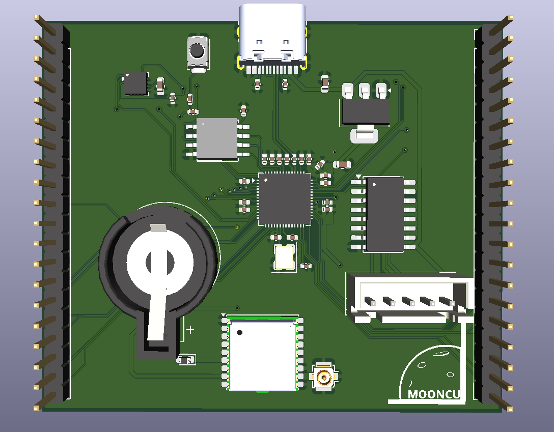 The first iteration of the development board.
The design of the board presented a lot of challenges. One of the biggest challenges was designing the GPS/RF portion of the board. This current iteration of the board uses a passive antenna. For optimal performance of the antenna, it is important to consider the trace length, width, and board thickness. However, once I learned about these necessary considerations it wasn’t too hard to calculate the necessary parameters and implement them into the design.
Another challenge I experienced was trace routing. In revision two of this board I would like to improve upon the routing and the overall layout of the board. For now however, this will do.
Lastly, finding components readily available in the US was a major hurdle. As of writing, shipping components from China can cost anywhere upwards of $40! So, sourcing parts in America has limited me to more expensive components that ship from sites like DigiKey.
Control Flow
With the board out of the way, the programming is relatively straight forward. 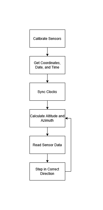 Simplified program control flow. For the most part, the lunar algorithm was first programmed in Python for and tested using information from the internet. Then I ported the program and the necessary look up tables over to C. Initially there was some challenge integrating the different functions together into one singular program, but there weren’t exactly any curveballs either. Once everything was put together programmatically I was able to test my software on a breadboard.
Prototype CAD
The main goal of this prototype design was to design something relatively compact and something I could possibly manufacture on my mini-lathe. I believe that the design shown below is a good step in the right direction as it achieved both of those goals. This prototype on the other hand, does not include the slip ring I plan to use to route the wires for the servo or the magnetometer that I plan on using. So, additional design work will need to be done before I can 3D print an initial mockup let alone machine it. 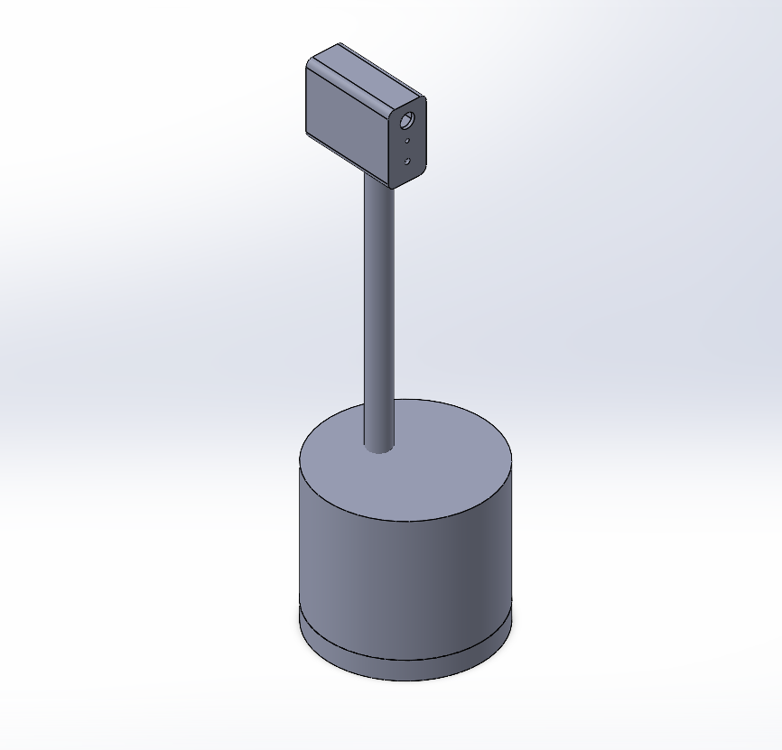 Prototype CAD
Final Remarks & Next Steps
This project is in a relatively good spot (in my opinion). The next steps for me are:
- Purchase PCB and components
- Assemble PCB
- Finish CAD redesign
- 3D print design
- Lathe necessary parts
Thank you for reading!